ROS2-MicroROS
Micro-ROS 即运行在微控制器上的 ROS 2,架构图如下:
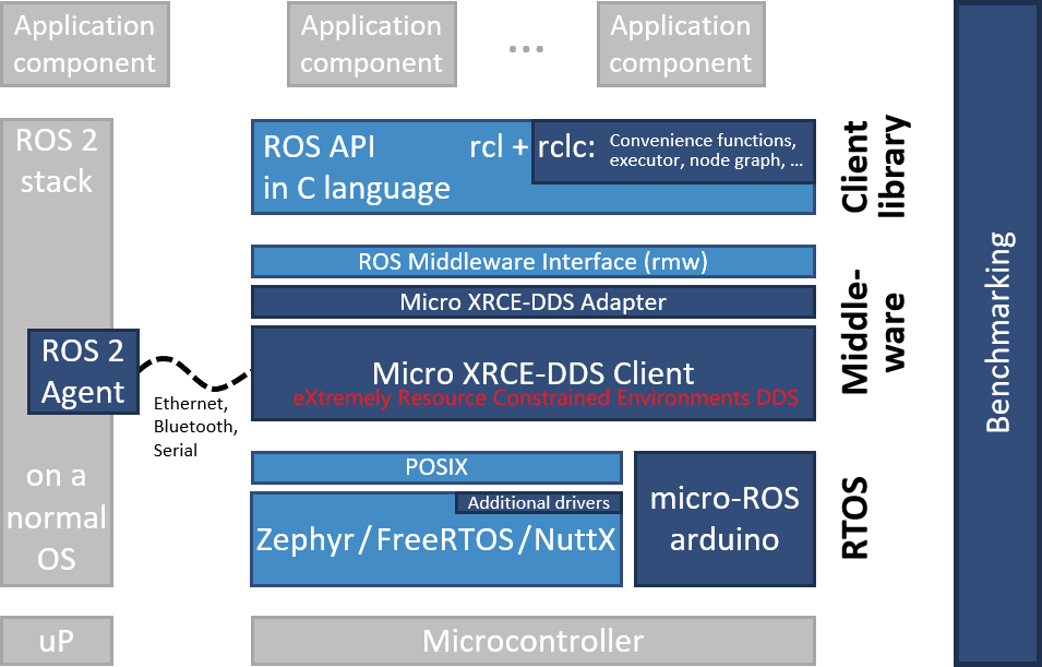
上位机运行Agent代理,微控制器可以通过串口,蓝牙、以太网、Wifi等多种协议将数据传递给Agent,Agent再将其转换成ROS2的话题等数据,以此完成通信。
第一个节点
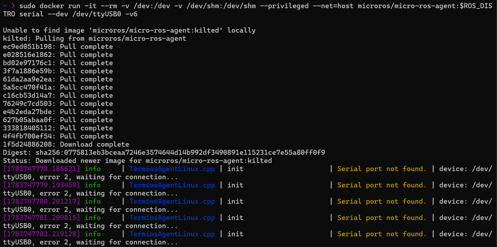
在docker中运行Micro-ROS的Agent:
sudo docker run -it --rm -v /dev:/dev -v /dev/shm:/dev/shm --privileged --net=host microros/micro-ros-agent:$ROS_DISTRO serial --dev /dev/ttyUSB0 -v6
Agent与烧录二进制文件不能同时进行
首次运行时会自动拉取microros/micro-ros-agent:$ROS_DISTRO镜像并运行,使用串口/dev/ttyUSB0与微控制器通信。
新建一个PlatformIO项目,开发板为Adafruit ESP32 Feather,在platformio.ini中添加如下依赖:
lib_deps =
    https://gitee.com/ohhuo/micro_ros_platformio.git
使用RCLC-API创建一个空节点,代码风格如下:
#include <Arduino.h>
#include <micro_ros_platformio.h>

#include <rcl/rcl.h>
#include <rclc/rclc.h>
#include <rclc/executor.h>

rclc_executor_t executor;
rclc_support_t support;
rcl_allocator_t allocator;
rcl_node_t node;

void setup()
{
  Serial.begin(115200);
  // 设置通过串口进行MicroROS通信
  set_microros_serial_transports(Serial);
  // 延时时一段时间,等待设置完成
  delay(2000);
  // 初始化内存分配器
  allocator = rcl_get_default_allocator();
  // 创建初始化选项
  rclc_support_init(&support, 0, NULL, &allocator);
  // 创建节点 hello_microros
  rclc_node_init_default(&node, "hello_microros", "", &support);
  // 创建执行器
  rclc_executor_init(&executor, &support.context, 1, &allocator);
}

void loop()
{
  delay(100);
  // 循环处理数据
  rclc_executor_spin_some(&executor, RCL_MS_TO_NS(100));
}
编译并上传代码到开发板,再次运行Micro-ROS Agent,查看Agent的输出(若是没有输出,则按下开发板上RST按钮):
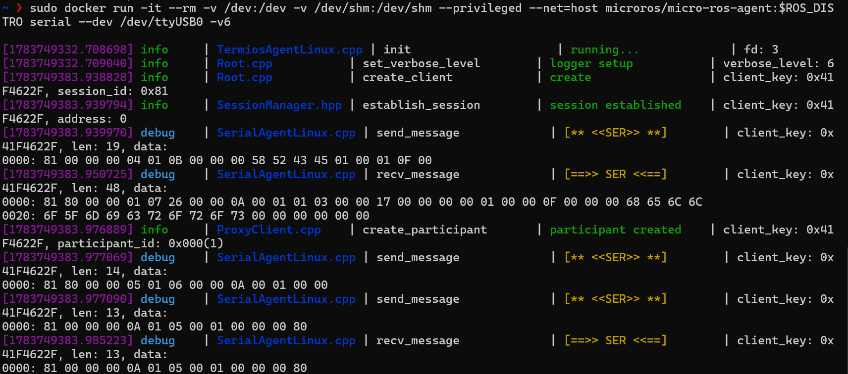
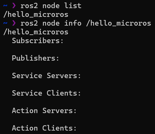
此时在上位机中可以看到/hello_microros节点。
Topic订阅
通过Topic控制LED灯的开关,代码如下:
#include <Arduino.h>
#include <micro_ros_platformio.h>

#include <rcl/rcl.h>
#include <rclc/rclc.h>
#include <rclc/executor.h>

#include <std_msgs/msg/int32.h>

rclc_executor_t executor;
rclc_support_t support;
rcl_allocator_t allocator;
rcl_node_t node;
// 声明话题订阅者
rcl_subscription_t subscriber;
// 声明消息文件
std_msgs__msg__Int32 sub_msg;
// 定义话题接收回调函数
void callback_subscription_(const void *msgin)
{
  const std_msgs__msg__Int32 *msg = (const std_msgs__msg__Int32 *)msgin;
  if (msg->data == 0)
  {
    digitalWrite(2, HIGH); // 关灯
  }
  else
  {
    digitalWrite(2, LOW);  // 开灯
  }
}

void setup()
{
  Serial.begin(115200);
  // 设置通过串口进行MicroROS通信
  set_microros_serial_transports(Serial);
  // 延时时一段时间,等待设置完成
  delay(2000);
  // 初始化内存分配器
  allocator = rcl_get_default_allocator();
  // 创建初始化选项
  rclc_support_init(&support, 0, NULL, &allocator);
  // 创建节点 topic_sub_test
  rclc_node_init_default(&node, "topic_sub_test", "", &support);
  // 订阅者初始化
  rclc_subscription_init_default(
      &subscriber,
      &node,
      ROSIDL_GET_MSG_TYPE_SUPPORT(std_msgs, msg, Int32),
      "led_control");
  // 创建执行器
  rclc_executor_init(&executor, &support.context, 1, &allocator);
  // 为执行器添加一个订阅者
  rclc_executor_add_subscription(&executor, &subscriber, &sub_msg, &callback_subscription_, ON_NEW_DATA);
  // 初始化LED
  pinMode(2, OUTPUT);
}

void loop()
{
  delay(100);
  // 循环处理数据
  rclc_executor_spin_some(&executor, RCL_MS_TO_NS(100));
}
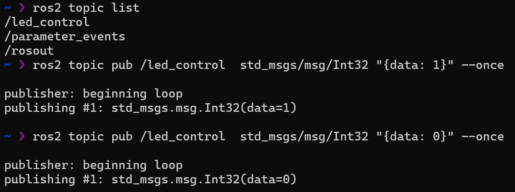
该代码实现了一个订阅者节点topic_sub_test,订阅话题led_control,接收到的消息为std_msgs/msg/Int32类型,若接收到的消息为0,则关闭LED灯,否则打开LED灯。
编译并上传代码到开发板,运行Micro-ROS Agent,此时在上位机中可以看到led_control话题,使用如下命令发布消息控制LED灯:
# 关闭LED灯
ros2 topic pub /led_control std_msgs/msg/Int32 "{data: 0}" --once
# 打开LED灯
ros2 topic pub /led_control std_msgs/msg/Int32 "{data: 1}" --once
Topic发布
编写代码发布电池电压到话题battery_voltage,代码如下:
#include <Arduino.h>
#include <micro_ros_platformio.h>

#include <rcl/rcl.h>
#include <rclc/rclc.h>
#include <rclc/executor.h>
// 消息类型头文件
#include <std_msgs/msg/float32.h>

rclc_executor_t executor;
rclc_support_t support;
rcl_allocator_t allocator;
rcl_node_t node;
rcl_timer_t timer;

// 声明话题发布者
rcl_publisher_t publisher;
// 声明消息文件
std_msgs__msg__Float32 pub_msg;

// 定义定时器接收回调函数
void timer_callback(rcl_timer_t *timer, int64_t last_call_time)
{
  RCLC_UNUSED(last_call_time);
  if (timer != NULL)
  {
    rcl_publish(&publisher, &pub_msg, NULL);
  }
}

void setup()
{
  Serial.begin(115200);
  // 设置通过串口进行MicroROS通信
  set_microros_serial_transports(Serial);
  // 延时时一段时间,等待设置完成
  delay(2000);
  // 初始化内存分配器
  allocator = rcl_get_default_allocator();
  // 创建初始化选项
  rclc_support_init(&support, 0, NULL, &allocator);
  // 创建节点 topic_pub_test
  rclc_node_init_default(&node, "topic_pub_test", "", &support);
  // 发布者初始化,发布std_msgs/msg/Float32消息到/battery_voltage
  rclc_publisher_init_default(
      &publisher,
      &node,
      ROSIDL_GET_MSG_TYPE_SUPPORT(std_msgs, msg, Float32),
      "battery_voltage");

  // 创建定时器,200ms发一次
  const unsigned int timer_timeout = 200;
  rclc_timer_init_default(
      &timer,
      &support,
      RCL_MS_TO_NS(timer_timeout),
      timer_callback);

  // 创建执行器
  rclc_executor_init(&executor, &support.context, 1, &allocator);
  // 给执行器添加定时器
  rclc_executor_add_timer(&executor, &timer);
  // 初始化ADC
  pinMode(34, INPUT);
  analogSetAttenuation(ADC_11db);
}

void loop()
{
  delay(100);
  // 循环处理数据
  rclc_executor_spin_some(&executor, RCL_MS_TO_NS(100));
  // 通过ADC获取电压值
  // int analogValue = analogRead(34);                     // 读取原始值0-4096
  int analogVolts = analogReadMilliVolts(34);           // 读取模拟电压,单位毫伏
  float realVolts = 5.02 * ((float)analogVolts * 1e-3); // 计算实际电压值
  pub_msg.data = realVolts; // 填充到发布消息结构
}
在该代码中,创建了一个发布者节点topic_pub_test,发布话题battery_voltage,消息类型为std_msgs/msg/Float32,通过ADC读取电压值并使用定时器发布。
编译并上传代码到开发板,运行Micro-ROS Agent,Agent日志中可看到持续接收到的数据,此时在上位机中可以看到battery_voltage话题,使用topic echo查看该话题消息:
ros2 topic echo /battery_voltage
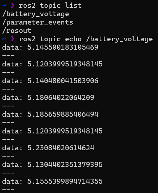
电压约为5V,符合预期。
Service
为节点添加两数相加示例服务,代码如下:
#include <Arduino.h>
#include <micro_ros_platformio.h>

#include <rcl/rcl.h>
#include <rclc/rclc.h>
#include <rclc/executor.h>

// 添加接口
#include <example_interfaces/srv/add_two_ints.h>

rclc_executor_t executor;
rclc_support_t support;
rcl_allocator_t allocator;
rcl_node_t node;

// 定义服务
rcl_service_t service;

// 服务请求和返回消息定义
example_interfaces__srv__AddTwoInts_Request req;
example_interfaces__srv__AddTwoInts_Response res;

// 服务回调函数
void service_callback(const void *req, void *res)
{
  example_interfaces__srv__AddTwoInts_Request *req_in = (example_interfaces__srv__AddTwoInts_Request *)req;
  example_interfaces__srv__AddTwoInts_Response *res_in = (example_interfaces__srv__AddTwoInts_Response *)res;
  // 计算sum
  res_in->sum = req_in->a + req_in->b;
}

void setup()
{
  Serial.begin(115200);
  // 设置通过串口进行MicroROS通信
  set_microros_serial_transports(Serial);
  // 延时时一段时间,等待设置完成
  delay(2000);
  // 初始化内存分配器
  allocator = rcl_get_default_allocator();
  // 创建初始化选项
  rclc_support_init(&support, 0, NULL, &allocator);
  // 创建节点 hello_microros
  rclc_node_init_default(&node, "service_test", "", &support);
  // 使用默认配置创建服务
  rclc_service_init_default(&service, &node, ROSIDL_GET_SRV_TYPE_SUPPORT(example_interfaces, srv, AddTwoInts), "/addtwoints");
  // 创建执行器
  rclc_executor_init(&executor, &support.context, 1, &allocator);
  // 执行器添加服务
  rclc_executor_add_service(&executor, &service, &req, &res, service_callback);
}

void loop()
{
  delay(100);
  // 循环处理数据
  rclc_executor_spin_some(&executor, RCL_MS_TO_NS(100));
}
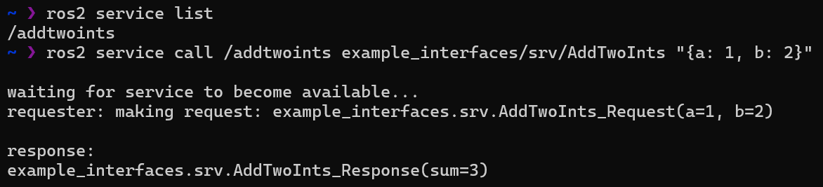
在该代码中,创建了一个服务节点service_test,提供服务/addtwoints,其中请求与响应的消息类型分别定义为
typedef struct example_interfaces__srv__AddTwoInts_Request
{
  int64_t a;
  int64_t b;
} example_interfaces__srv__AddTwoInts_Request;

typedef struct example_interfaces__srv__AddTwoInts_Response
{
  int64_t sum;
} example_interfaces__srv__AddTwoInts_Response;
此时在上位机中可以看到/addtwoints服务,使用如下命令调用该服务:
ros2 service call /addtwoints example_interfaces/srv/AddTwoInts "{a: 1, b: 2}"
Interface
本节尝试自定义接口,并使用该接口创建服务控制OLED显示指定文字
添加依赖
创建一个新的PlatformIO项目,开发板为Adafruit ESP32 Feather,在platformio.ini中添加如下依赖:
lib_deps =
    https://gitee.com/ohhuo/micro_ros_platformio.git
    adafruit/Adafruit SSD1306@^2.5.7
创建自定义接口功能包
在工程目录下创建名为extra_packages的文件夹,该文件夹中的ros包会被添加进编译过程。在extra_packages中创建ros功能包:
mkdir extra_packages
cd extra_packages
ros2 pkg create fishbot_interfaces
添加自定义接口文件extra_packages/fishbot_interfaces/srv/OledControl.srv,内容如下:
int32 px
int32 py
string data
---
int32 result
修改功能包CMakeLists.txt,添加如下内容:
find_package(rosidl_default_generators REQUIRED)

rosidl_generate_interfaces(${PROJECT_NAME}
  "srv/OledControl.srv"
 )
修改功能包package.xml,添加如下内容:
<build_depend>rosidl_default_generators</build_depend>
<exec_depend>rosidl_default_runtime</exec_depend>
<member_of_group>rosidl_interface_packages</member_of_group>
编译功能包:
cd extra_packages
colcon build --packages-select fishbot_interfaces
重新编译
删除工程目录下的.pio/libdeps/featheresp32/micro_ros_platformio/libmicroros文件夹,重新编译,以添加extra_packages中的自定义接口
若过程中fishros服务器返回503错误
fatal: unable to access 'http://github.fishros.org/https://github.com/ament/ament_cmake/': The requested URL returned error: 503
可尝试换用micro-ROS-platformio官方源,并进行如下修改:
- 修改依赖中的micro_ros_platformio库地址为官方源:
https://github.com/micro-ROS/micro_ros_platformio.git - 出现
SetuptoolsDeprecationWarning,要屏蔽该警告可降级Setuptools版本:
# 使用实际的penv路径执行
/root/.platformio/penv/bin/pip install "setuptools<70.0.0"
- 出现
rmw_test_fixture CMake Error,要跳过该错误可跳过编译该桌面端测试包
# 方法一:
touch .pio/libdeps/featheresp32/micro_ros_platformio/build/dev/src/ament_cmake_ros/rmw_test_fixture/COLCON_IGNORE
# 方法二:在所有名为rmw_test_fixture的文件夹中创建COLCON_IGNORE文件
find .pio -name "rmw_test_fixture" -type d -exec touch {}/COLCON_IGNORE \;
- 再次重新编译,若出错则需删除已编译
build文件夹后重新编译。
创建服务节点
创建服务节点hello_interface,提供服务/oled_control,代码如下:
#include <Arduino.h>
#include <micro_ros_platformio.h>

#include <rcl/rcl.h>
#include <rclc/rclc.h>
#include <rclc/executor.h>
#include <micro_ros_utilities/string_utilities.h> // string工具类,用于为string类型消息分配空间

#include "Wire.h"
#include <Adafruit_GFX.h>     // 加载Adafruit_GFX库
#include <Adafruit_SSD1306.h> // 加载Adafruit_SSD1306库

#include <fishbot_interfaces/srv/oled_control.h> // 接口文件

rclc_executor_t executor;
rclc_support_t support;
rcl_allocator_t allocator;
rcl_node_t node;
// 定义服务
rcl_service_t service;

// 服务请求和返回消息定义
fishbot_interfaces__srv__OledControl_Request req;
fishbot_interfaces__srv__OledControl_Response res;

Adafruit_SSD1306 display;

// 服务回调函数
void service_callback(const void *req, void *res)
{
  // 将void指针转换为具体类型
  fishbot_interfaces__srv__OledControl_Request *req_in = (fishbot_interfaces__srv__OledControl_Request *)req;
  fishbot_interfaces__srv__OledControl_Response *res_in = (fishbot_interfaces__srv__OledControl_Response *)res;
  // 执行显示操作
  display.clearDisplay();                    // 清空屏幕
  display.setCursor(req_in->px, req_in->py); // 设置开始显示文字的坐标
  display.println(req_in->data.data);        // 输出的字符
  display.display();
  res_in->result = 0;
}

void setup()
{
  Serial.begin(115200);
  // 设置通过串口进行MicroROS通信
  set_microros_serial_transports(Serial);
  // 延时时一段时间,等待设置完成
  delay(2000);
  // 初始化内存分配器
  allocator = rcl_get_default_allocator();
  // 创建初始化选项
  rclc_support_init(&support, 0, NULL, &allocator);
  // 创建节点 hello_interface
  rclc_node_init_default(&node, "hello_interface", "", &support);
  // 使用默认配置创建服务
  rclc_service_init_default(&service, &node, ROSIDL_GET_SRV_TYPE_SUPPORT(fishbot_interfaces, srv, OledControl), "/oled_control");
  // 创建执行器
  rclc_executor_init(&executor, &support.context, 1, &allocator);
  // 执行器添加服务
  rclc_executor_add_service(&executor, &service, &req, &res, service_callback);
  // 重要,为string类型消息分配空间
  req.data = micro_ros_string_utilities_init_with_size(100);

  /*========================OLED初始化====================================*/
  Wire.begin(18, 19);
  display = Adafruit_SSD1306(128, 64, &Wire);
  display.begin(SSD1306_SWITCHCAPVCC, 0x3C); // 设置OLED的I2C地址
  display.clearDisplay();                    // 清空屏幕
  display.setTextSize(1);                    // 设置字体大小
  display.setCursor(0, 0);                   // 设置开始显示文字的坐标
  display.setTextColor(SSD1306_WHITE);       // 设置字体颜色
  display.println("hello fishros!");         // 输出的字符
  display.display();
}

void loop()
{
  delay(100);
  // 循环处理数据,等待服务调用
  rclc_executor_spin_some(&executor, RCL_MS_TO_NS(100));
}
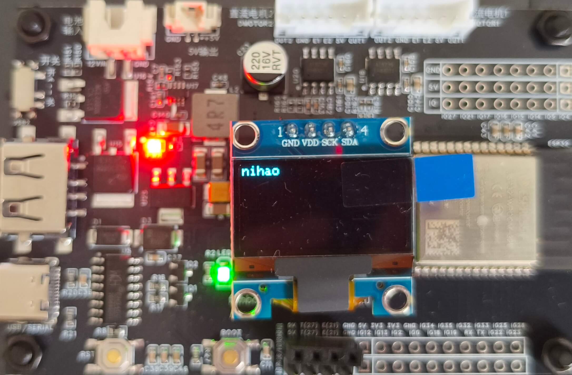
该代码创建了一个服务节点hello_interface,提供服务/oled_control,其中micro_ros_string_utilities_init_with_size为string类型消息分配了空间
编译烧录代码到开发板,运行Micro-ROS Agent,此时在上位机中可以看到/oled_control服务,使用如下命令调用该服务:
source 项目路径/extra_packages/install/setup.bash # 加载自定义接口环境
ros2 service call /oled_control fishbot_interfaces/srv/OledControl "{px: 0, py: 0 , data: 'nihao'}" # 以(0,0)为起点显示文字"nihao"

Time库
本节尝试使用Time库获取时间,并将时钟显示在OLED屏幕上。
Time库函数常见用法:
- year()/month()/day()/hour()/minute()/second():获取当前时间的年/月/日/时/分/秒,返回值为整数int
- rmw_uros_epoch_synchronized():判断时间是否同步
- rmw_uros_sync_session(timeout_ms):使用NTP协议同步时间,参数为超时时间
- rmw_uros_epoch_millis():获取当前时间,单位为毫秒
- setTime(time_t t):设置当前时间,参数为秒
时钟同步测试
添加依赖paulstoffregen/Time@^1.6.1:
lib_deps =
    https://gitee.com/ohhuo/micro_ros_platformio.git
    adafruit/Adafruit SSD1306@^2.5.7
    paulstoffregen/Time@^1.6.1
编写代码:
#include <Arduino.h>
#include <micro_ros_platformio.h>

#include <rcl/rcl.h>
#include <rclc/rclc.h>
#include <rclc/executor.h>

#include <TimeLib.h>          // 加载时间库,提供setTime\year\month...函数
#include <Adafruit_GFX.h>     // 加载Adafruit_GFX库
#include <Adafruit_SSD1306.h> // 加载Adafruit_SSD1306库
Adafruit_SSD1306 display;     // 声明对象

rclc_executor_t executor;
rclc_support_t support;
rcl_allocator_t allocator;
rcl_node_t node;

const int timeout_ms = 1000;  // 超时时间:1s
static int64_t time_ms;       // 毫秒
static time_t time_seconds;   // 秒
char time_str[25];            // 时间显示的字符串

void setup()
{
  Serial.begin(115200);
  // 设置通过串口进行MicroROS通信
  set_microros_serial_transports(Serial);
  // 延时时一段时间,等待设置完成
  delay(2000);
  // 初始化内存分配器
  allocator = rcl_get_default_allocator();
  // 创建初始化选项
  rclc_support_init(&support, 0, NULL, &allocator);
  // 创建节点 time_sync
  rclc_node_init_default(&node, "time_sync", "", &support);
  // 创建执行器
  rclc_executor_init(&executor, &support.context, 1, &allocator);

  Wire.begin(18, 19);
  display = Adafruit_SSD1306(128, 64, &Wire);
  display.begin(SSD1306_SWITCHCAPVCC, 0x3C); // 设置OLED的I2C地址,默认0x3C
  display.setTextSize(2);                    // 设置字体大小,最小为1
  display.clearDisplay();                    // 清空屏幕
  display.setCursor(0, 0);                   // 设置开始显示文字的坐标
  display.setTextColor(SSD1306_WHITE);       // 设置字体颜色
  display.println("hello oled!");            // 输出的字符
}

void loop()
{
  /*=========================同步时间=====================================*/
  while (!rmw_uros_epoch_synchronized()) // 判断时间是否同步
  {
    rmw_uros_sync_session(timeout_ms); //  同步时间
    if (rmw_uros_epoch_synchronized())
    {
      time_ms = rmw_uros_epoch_millis(); // 获取当前时间(毫秒)
      time_seconds = time_ms / 1000;     // 转换为秒
      setTime(time_seconds + 8 * 3600); // 将当前时间+8H到北京时间然后设置到系统
    }
    delay(10);
    return;
  }

  /*========================获取时间与显示==================================*/
  sprintf(time_str, "%04d-%02d-%02d %02d:%02d:%02d ", year(), month(), day(), hour(), minute(), second());

  display.clearDisplay();    // 清空屏幕
  display.setCursor(00, 0);  // 设置开始显示文字的坐标
  display.println(time_str); // 输出的字符
  display.display();
  delay(100);
}
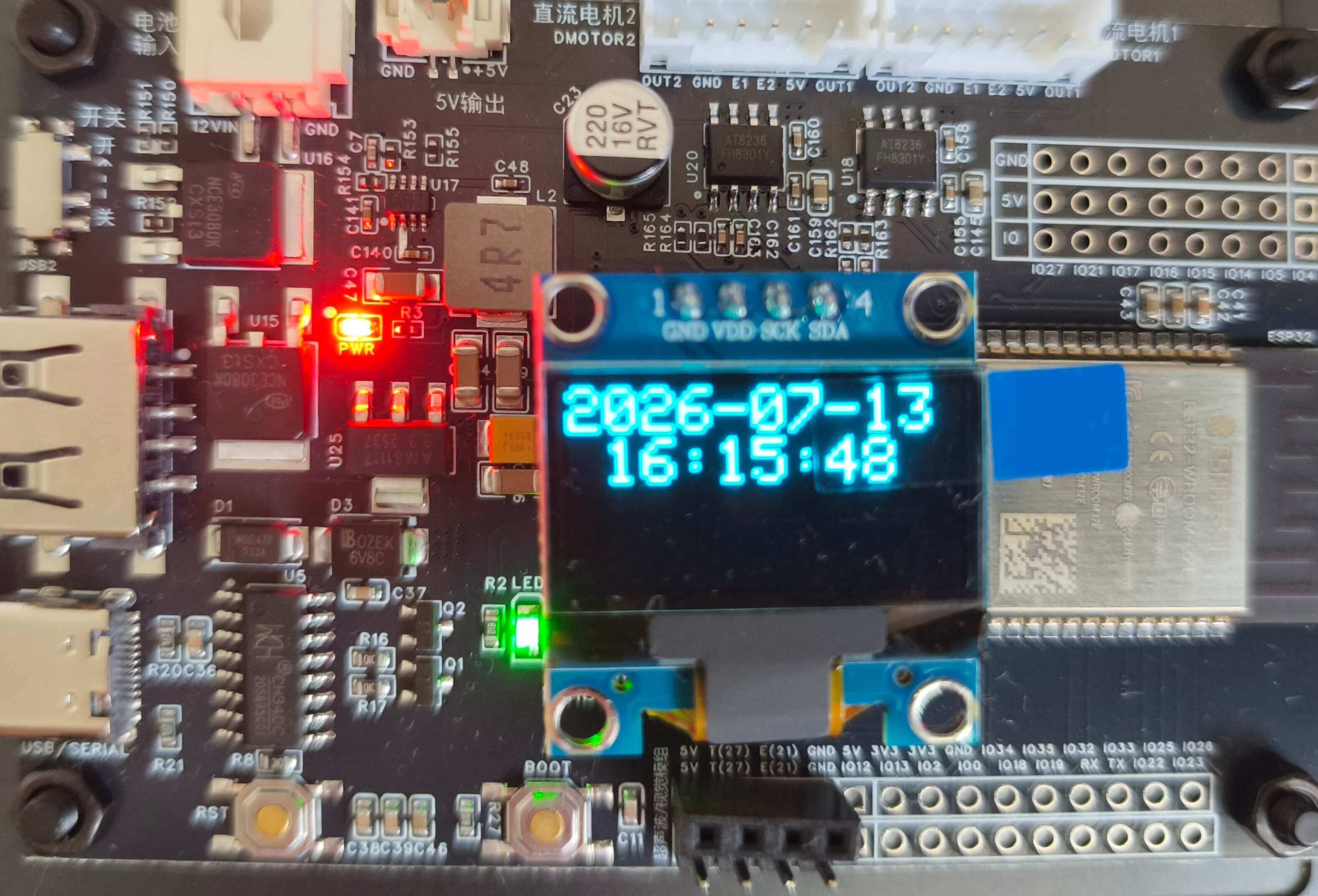
编译并上传代码到开发板,运行Micro-ROS Agent,此时在OLED屏幕上可以看到当前时间,看不到可点击RST按钮。
无线通信-WiFi
本节尝试使用WiFi替代串口进行Micro-ROS通信。
相较于串口通信的set_microros_serial_transports函数,WiFi通信需要在代码中设置Agent的IP地址和端口号,函数声明如下
// 设置wifi名称、密码,Agent IP、端口号
void set_microros_wifi_transports(char * ssid, char * pass, IPAddress agent_ip, uint16_t agent_port)
无线通信测试
修改platformio.ini,添加依赖并配置WiFi通信:
board_microros_transport = wifi
lib_deps =
    https://gitee.com/ohhuo/micro_ros_platformio.git
    adafruit/Adafruit SSD1306@^2.5.7
    paulstoffregen/Time@^1.6.1
使用WiFi通信同步时钟,示例代码如下:
#include <Arduino.h>
#include <micro_ros_platformio.h>

#include <rcl/rcl.h>
#include <rclc/rclc.h>
#include <rclc/executor.h>

#include <WiFi.h>   // 无线通信库

#include <TimeLib.h>          // 加载时间库,提供setTime\year\month...函数
#include <Adafruit_GFX.h>     // 加载Adafruit_GFX库
#include <Adafruit_SSD1306.h> // 加载Adafruit_SSD1306库
Adafruit_SSD1306 display;     // 声明对象

rclc_executor_t executor;
rclc_support_t support;
rcl_allocator_t allocator;
rcl_node_t node;

const int timeout_ms = 1000;  // 超时时间:1s
static int64_t time_ms;       // 毫秒
static time_t time_seconds;   // 秒
char time_str[25];            // 时间显示的字符串

void setup()
{
  Serial.begin(115200);
  delay(1000); // 等待串口监视器打开
  Serial.println("\n===== Micro-ROS Time Sync OLED =====");

  // ---------- WiFi 连接与调试 ----------
  IPAddress agent_ip;
  agent_ip.fromString("10.28.8.94");  // 替换为实际的Agent运行主机的IP地址
  Serial.print("目标 Agent IP: ");
  Serial.println(agent_ip);

  Serial.println("正在启动 WiFi 传输...");
  // 设置 WiFi 名称,密码,Agent IP,端口号
  set_microros_wifi_transports("fish", "12345678", agent_ip, 8888);

  // 等待 WiFi 连接,并输出状态
  int connect_attempts = 0;
  while (WiFi.status() != WL_CONNECTED && connect_attempts < 20) {
    delay(1000);
    Serial.print(".");
    connect_attempts++;
  }
  Serial.println();

  if (WiFi.status() == WL_CONNECTED) {
    Serial.print("当前 IP 地址: ");
    Serial.println(WiFi.localIP());
  } else {
    Serial.println("WiFi 连接失败");
    while (1) {
      delay(1000);
    }
  }

  // 初始化内存分配器
  allocator = rcl_get_default_allocator();
  // 创建初始化选项
  rclc_support_init(&support, 0, NULL, &allocator);
  // 创建节点 wifi_test
  rclc_node_init_default(&node, "wifi_test", "", &support);
  // 创建执行器
  rclc_executor_init(&executor, &support.context, 1, &allocator);

  Wire.begin(18, 19);
  display = Adafruit_SSD1306(128, 64, &Wire);
  display.begin(SSD1306_SWITCHCAPVCC, 0x3C); // 设置OLED的I2C地址,默认0x3C
  display.setTextSize(2);                    // 设置字体大小,最小为1
  display.clearDisplay();                    // 清空屏幕
  display.setCursor(0, 0);                   // 设置开始显示文字的坐标
  display.setTextColor(SSD1306_WHITE);       // 设置字体颜色
  display.println("hello oled!");            // 输出的字符
  display.display();

  Serial.println("初始化完成,进入 loop...");
}

void loop()
{
  /*=========================同步时间=====================================*/
  if (!rmw_uros_epoch_synchronized()) {       // 判断时间是否同步
    rmw_uros_sync_session(timeout_ms);        // 同步时间
    if (rmw_uros_epoch_synchronized()) {
      time_ms = rmw_uros_epoch_millis();      // 获取当前时间(毫秒)
      time_seconds = time_ms / 1000;          // 转换为秒
      setTime(time_seconds + 8 * 3600);       // 转换为北京时间
      Serial.println("时间同步成功");
    }
    delay(10);
    return;
  }

  /*========================获取时间与显示==================================*/
  sprintf(time_str, "%04d-%02d-%02d %02d:%02d:%02d ", year(), month(), day(), hour(), minute(), second());

  display.clearDisplay();    // 清空屏幕
  display.setCursor(0, 0);   // 设置开始显示文字的坐标
  display.println(time_str); // 输出的字符
  display.display();
  delay(100);
}
将Agent的IP地址修改为实际的Agent运行主机的IP地址,编译并上传代码到开发板,
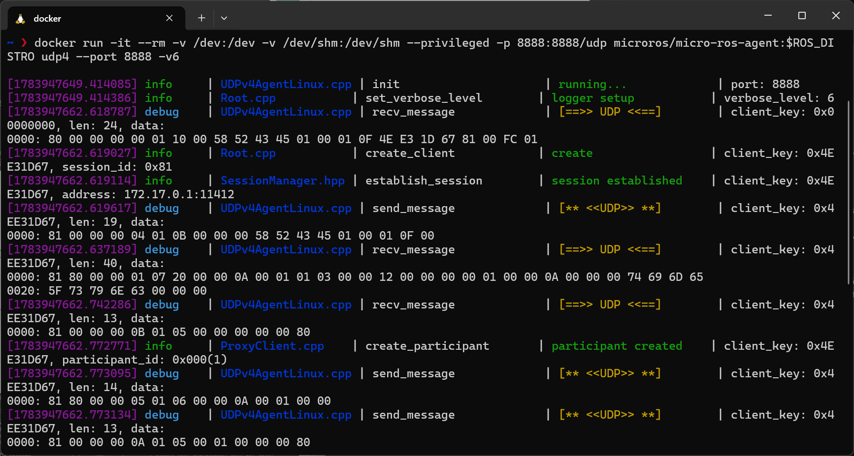
运行Micro-ROS Agent的命令与串口不同,需切换通信方式(UDP,IPv4,监听端口8888):
docker run -it --rm -v /dev:/dev -v /dev/shm:/dev/shm --privileged --net=host microros/micro-ros-agent:$ROS_DISTRO udp4 --port 8888 -v6
Agent会接收到来自开发板的WiFi通信数据,并同步时间,OLED屏幕上会显示当前时间。
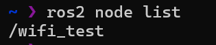
上位机中可以看到/wifi_test节点。
注意事项:
1. 确保开发板与运行Agent的主机连接同一WiFi网络。
2. 确保临时关闭防火墙,或配置规则允许UDP端口8888的通信。
3. 若使用WSL2运行Agent,需配置端口映射或使用mirror网络模式。
双核运行
ESP32单片机有两个内核,所有的外设都通过一个总线连接到两个内核上,也就是说,程序无论在哪个核上运行都可以操作硬件。
常用函数:
- xPortGetCoreID(): 获取当前运行的核心ID,返回值为0或1
- xTaskCreatePinnedToCore():创建任务并绑定到指定核心上运行。
xTaskCreatePinnedToCore()函数原型:
BaseType_t xTaskCreatePinnedToCore(
    TaskFunction_t pvTaskCode, // 任务函数
    const char * const pcName, // 任务名称
    const uint32_t usStackDepth, // 任务栈大小
    void * const pvParameters, // 传递给任务函数的参数
    UBaseType_t uxPriority, // 任务优先级
    TaskHandle_t * const pvCreatedTask, // 返回创建的任务句柄
    const BaseType_t xCoreID // 指定运行的核心ID,0或1
);
双核运行测试
修改platformio.ini,提高主频:
board_build.f_cpu = 240000000L
board_microros_transport = wifi
lib_deps =
    https://gitee.com/ohhuo/micro_ros_platformio.git
测试双核可用,代码如下:
#include <Arduino.h>

void microros_task(void *param)
{
  while (true)
  {
    delay(1000);
    Serial.printf("microros_task on core:%d\n", xPortGetCoreID());
  }
}

void setup()
{
  Serial.begin(115200);
  xTaskCreatePinnedToCore(microros_task, "microros_task", 10240, NULL, 1, NULL, 0);
}

void loop()
{
  delay(1000);
  Serial.printf("loop on core:%d\n", xPortGetCoreID());
}
以上代码创建了一个任务microros_task,绑定到核心0上运行,而loop()函数默认在核心1上运行。
编译并上传代码到开发板,打开串口监视器,能看到两个核心交替输出的日志:
microros_task on core:0
loop on core:1
microros_task on core:0
loop on core:1
...
在Micro-ROS中使用双核,代码如下:
#include <Arduino.h>
#include <micro_ros_platformio.h>
#include <WiFi.h>
#include <rcl/rcl.h>
#include <rclc/rclc.h>
#include <rclc/executor.h>

rclc_executor_t executor;
rclc_support_t support;
rcl_allocator_t allocator;
rcl_node_t node;

void microros_task(void *param)
{
  // 设置通过WIFI进行MicroROS通信
  IPAddress agent_ip;
  agent_ip.fromString("10.28.8.94");
  // 设置wifi名称,密码,电脑IP,端口号
  set_microros_wifi_transports("fish", "lhysz250213", agent_ip, 8888);
  // 延时时一段时间,等待设置完成
  delay(2000);
  // 初始化内存分配器
  allocator = rcl_get_default_allocator();
  // 创建初始化选项
  rclc_support_init(&support, 0, NULL, &allocator);
  // 创建节点 microros_wifi
  rclc_node_init_default(&node, "microros_wifi", "", &support);
  // 创建执行器
  rclc_executor_init(&executor, &support.context, 1, &allocator);
  while (true)
  {
    delay(100);
    Serial.printf("microros_task on core:%d\n", xPortGetCoreID());
    // 循环处理数据
    rclc_executor_spin_some(&executor, RCL_MS_TO_NS(100));
  }
}

void setup()
{
  Serial.begin(115200);
  xTaskCreatePinnedToCore(microros_task, "microros_task", 10240, NULL, 1, NULL, 0);
}

void loop()
{
  delay(1000);
  Serial.printf("do some control on core:%d\n", xPortGetCoreID());
}
以上代码创建了一个任务microros_task,创建了一个空节点microros_wifi绑定到核心0上运行,而loop()函数默认在核心1上运行,loop()函数中可以执行一些控制逻辑。
编译并上传代码到开发板,可以看到两个核心交替输出的日志:
microros_task on core:0
microros_task on core:0
do some control on core:1
microros_task on core:0
microros_task on core:0
microros_task on core:0
留言